Control
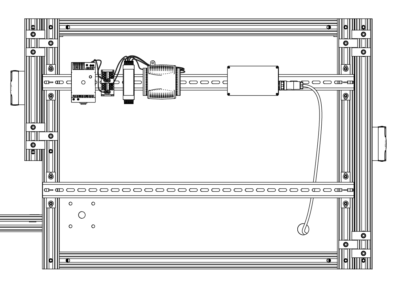
The control module consist on a 24V power source, a couple of distribution blocks, which make it easier to connect any other stuff that works on 24V; a custom made solenoid valve driver, an USB NiDAQ card from National Instruments and an Arduino due that is inside a 3D printed housing with a DIN rail clip attached. Each of these parts will be explained in detail below with instructions for assembly.
Solenoid valve driver assembly
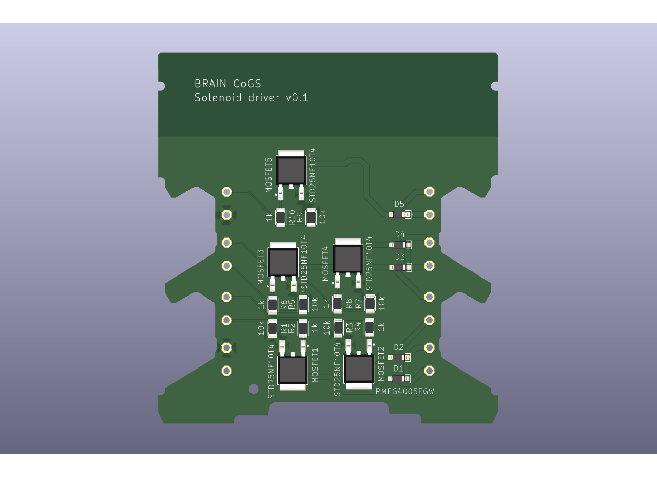
We designed a simple solenoid valve driver circuit using a MOSFET, the gate is driven by a digital input that will be supplied by the NIDAQ card, which open and closes the circuit from the solenoid valve to a 24V power supply. We added a diode to protect the circuit from discharge from the solenoid valve. To assembly the solenoid valve driver follow the next steps.
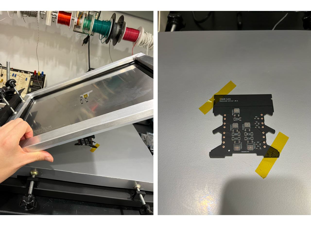
- Have the PCB made (we use pcbway since they can make and ship the stencil, you can found our project here) and make sure to order a stencil. We use a manual printer for PCB stencil to spread the soldering paste across the PCB pads evenly. First, place the PCB on the surface using high temperature tape and place the stencil on top of it. Make sure to match the solder pads to the holes of the stencil.
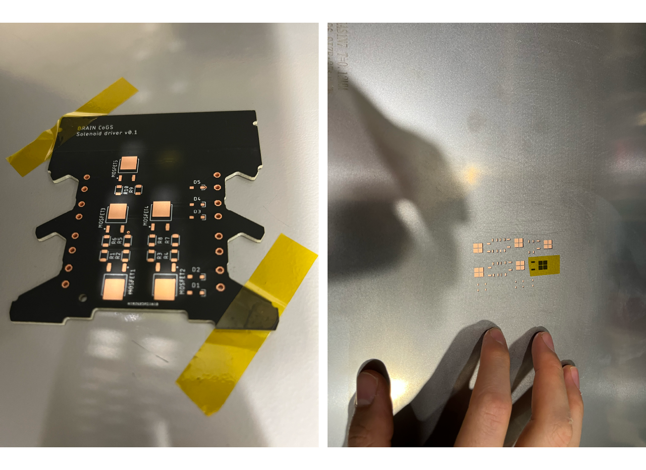
- Use solder paste and a flexible wipe down knife and spread evenly the solder paste into the pads. Then lift and remove the stencil.
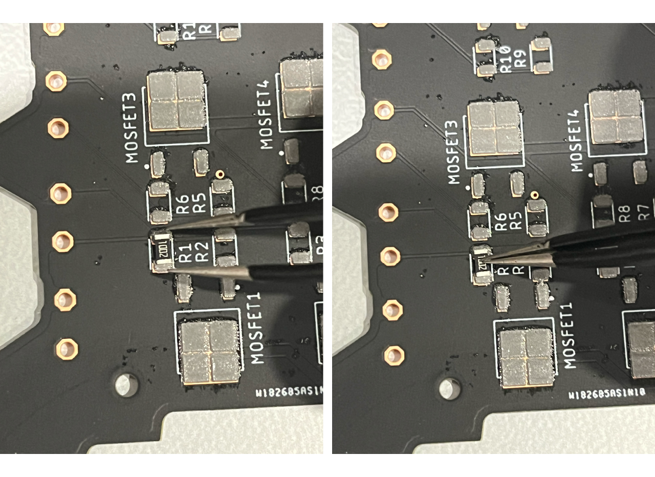
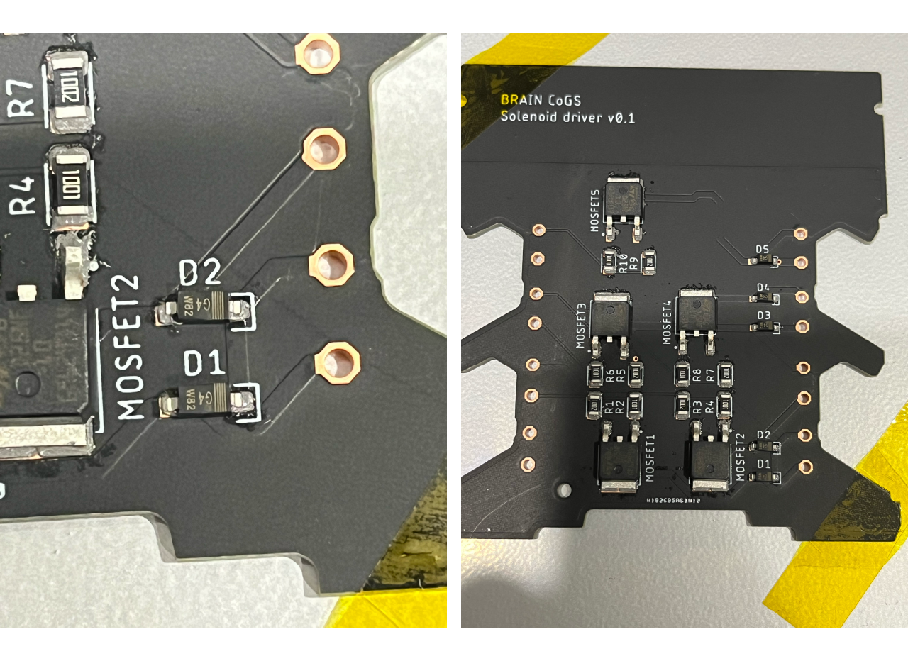
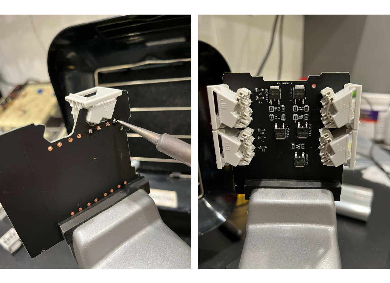
- Place each component into place, we place the resistances (R1, R3, R5, R7, and R9 resistor values are 10K Ohm and R2, R4, R6, R8 and R10 resistor values are 1K Ohm) first, then place the MOSFET and finally the diodes, make sure that the diodes are placed correctly (the band should match the ] symbol on the PCB). The picture below show the correct position of the components.
TIP
Each time you place a component in the pad make sure to slightly press it against the solder paste with the same tweezers that you use.
- Use a heat gun (we set the temperature at 1000F) at the lowest intensity allowed (to avoid components flying around) and move it around on top of the components until the solder melt and the components get attached in place.
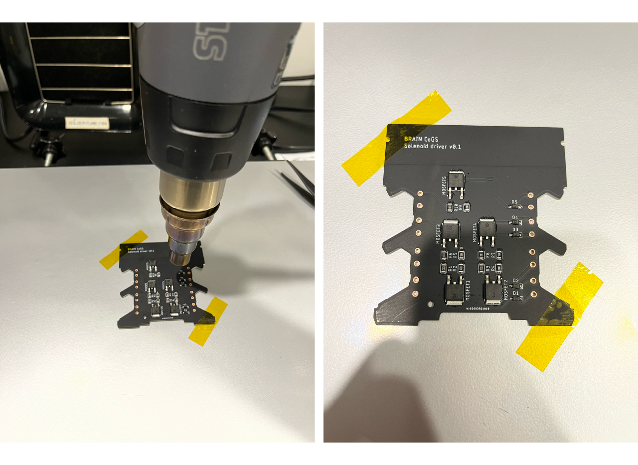
- Remove the high temperature tape and solder the pluggable terminal blocks, place the fillers and slide down the PCB into the case, then close the case.
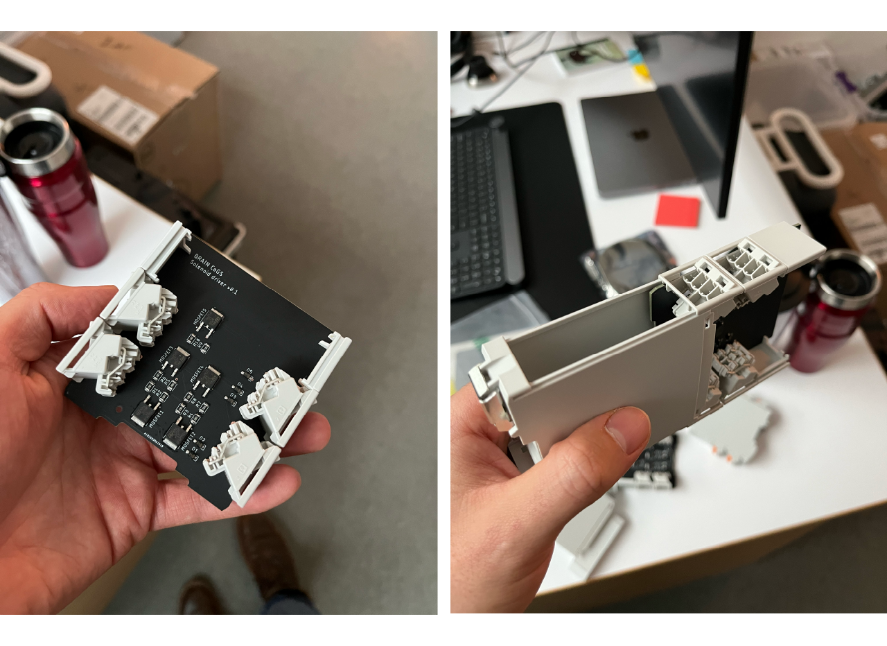
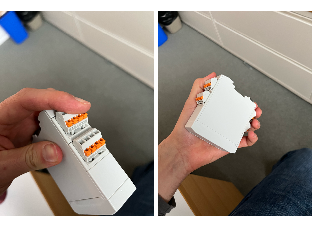
- Place the labels (make sure they are placed correctly) and place the driver on the DIN rail.
Power supply and NIDAQ control assembly
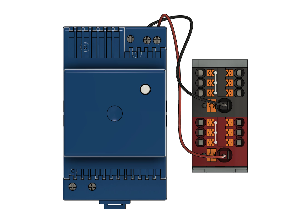
- Place the power supply and the distribution blocks on the DIN rails, connect the power supply to the distribution block input accordigly. The TRACO Power TBLC 50-124 is a 50W power supply, which is more than enough to power both the reward module solenoid valve (7 Watts) and the two air puffs solenoid valves (0.65 Watts each one), and have plenty of power left (~40W) for other modules if required. One power supply could be use for a stack of 2 or 3 rigs if desired.
TIP
Use a standard PC power cable and cut the portion of the connector that goes to the PC, cut the ground cable and connect the neutral cable to the negative input of the power supply and the hot cable to the positive input.
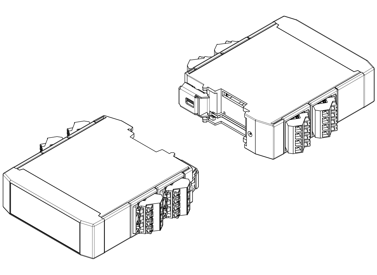
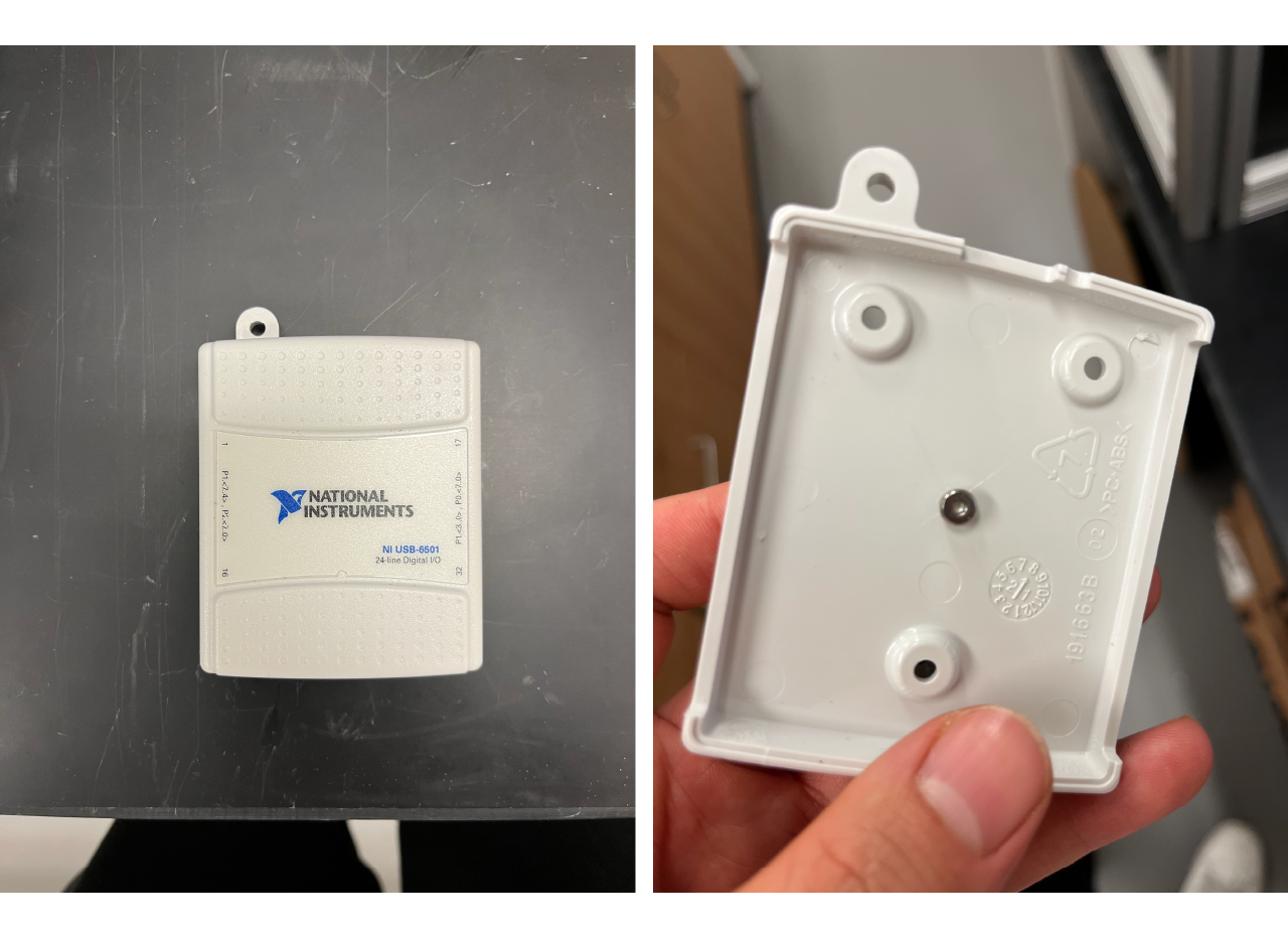
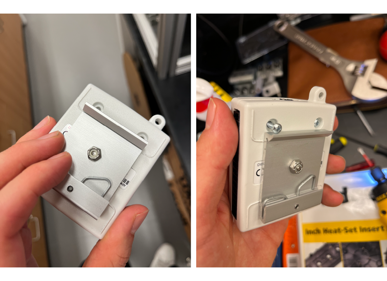
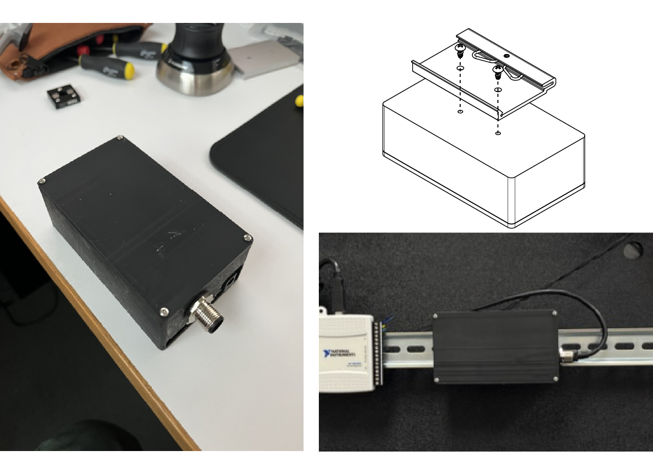
- Open the NIDAQ case and make a hole at the middle of the back case. Screw the DIN rail mounting clip to it, then close the case and place the top screws only.
- Connect everything!
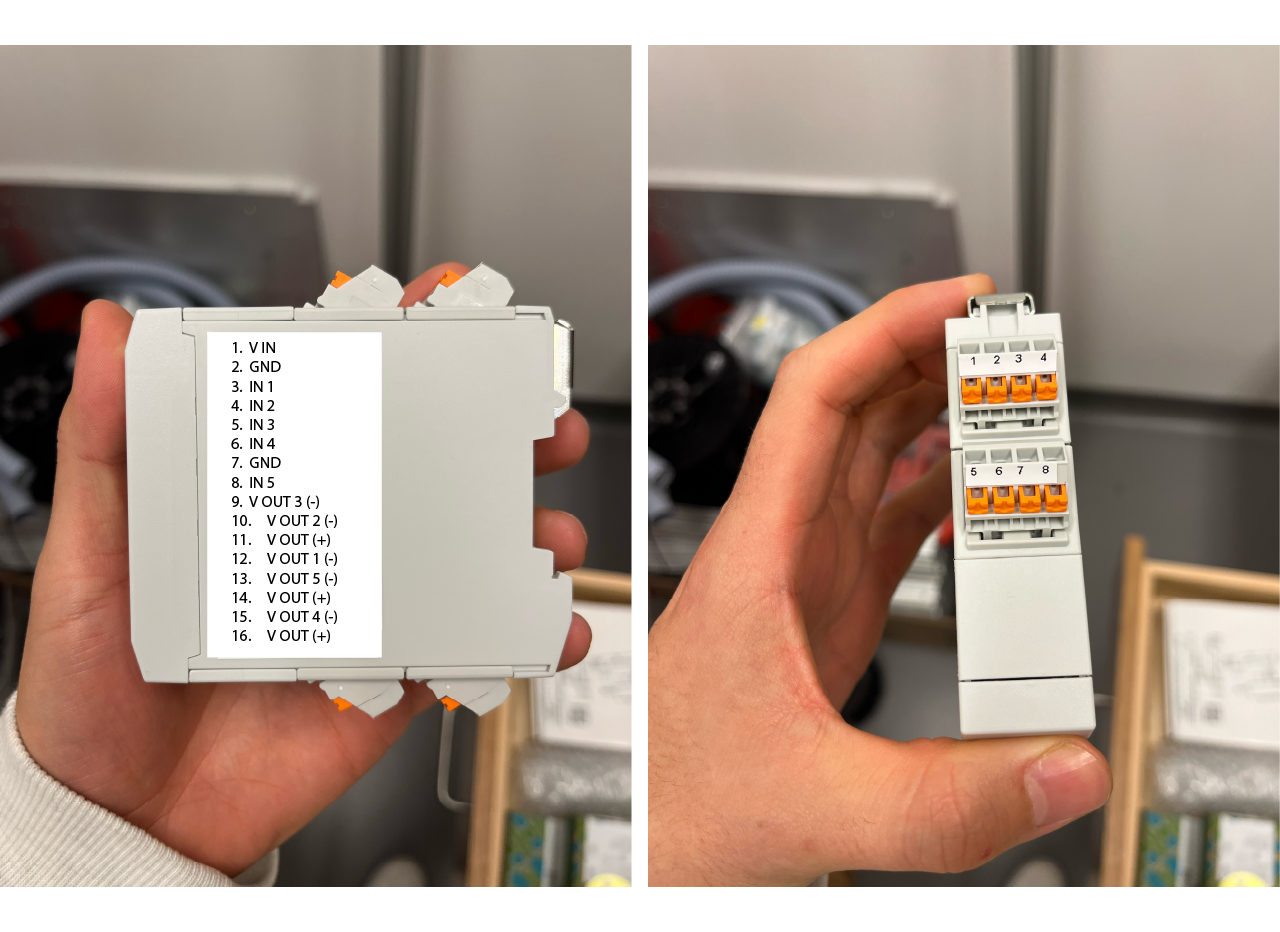
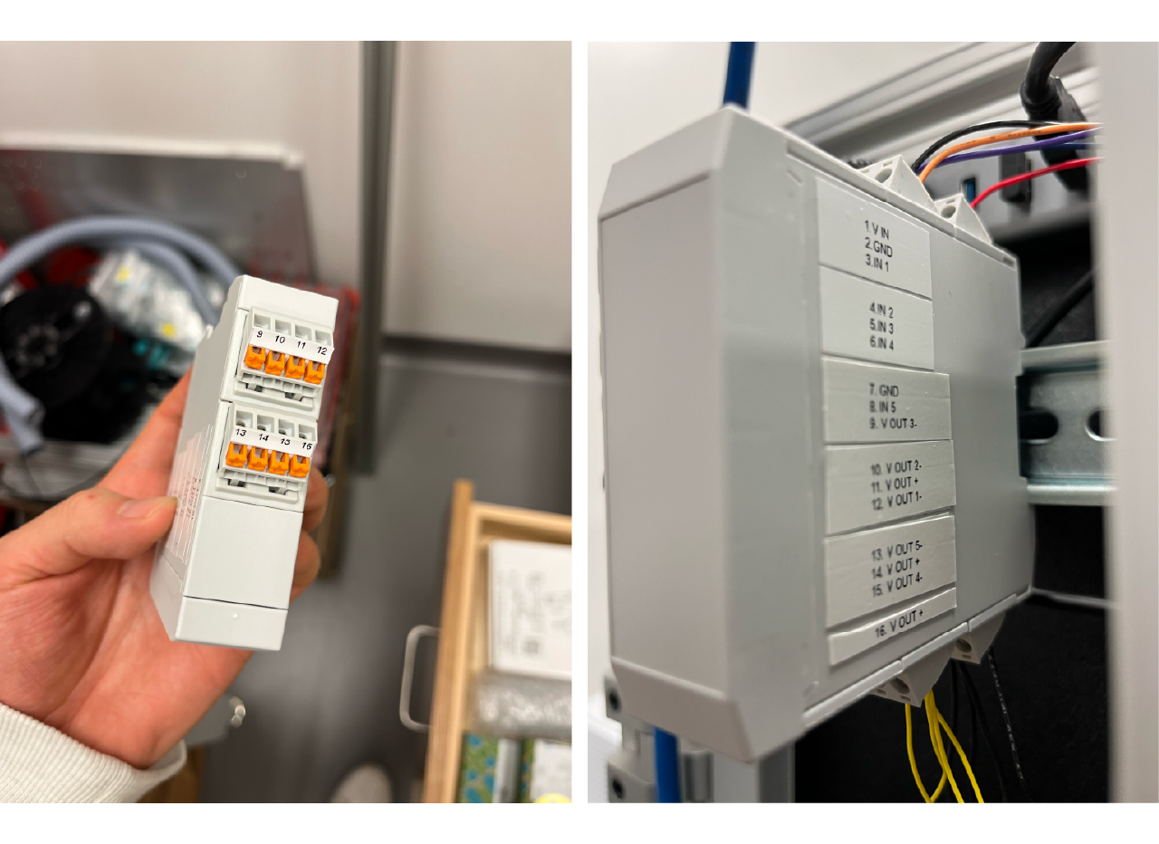
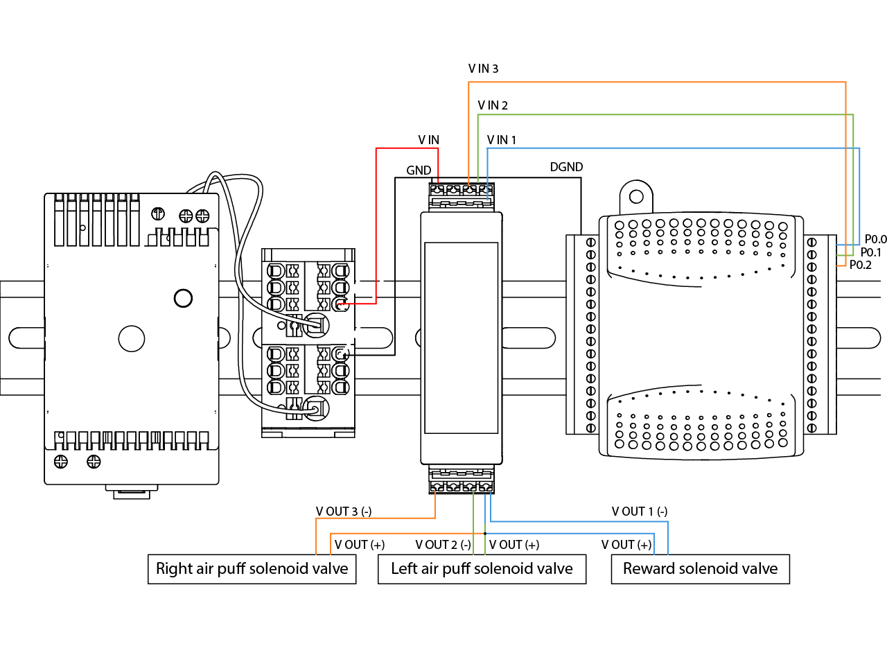
- Start by connecting the positive output of the power supply from one of the pins of the red distribution blocks to the V IN input of the solenoid valve driver, then the ground from one of the pins of the black distribution block to the GND pin of the solenoid valve driver.
- Then connect the one of the GND pins of the solenoid valve driver to the the digital ground pin of the NIDAQ.
- Connect the solenoid valve driver inputs to the NIDAQ outputs as follows: P0.0 from NIDAQ to V IN 1, P0.1 to V IN 2 and P0.2 to V IN 3.
- Finally connect the solenoid valve driver outputs to the solenoid valve drivers. Since the solenoid valves doesn't have polarity, you should use the V OUT (+) as common in the valves, you can use one or multiple pins of the solenoid valve driver. Then connect the V OUT 1 (-) pin to the reward solenoid valve, the V OUT 2 (-) pin to the left solenoid valve and the V OUT 3 (-) to the right solenoid valve.
TIP
The solenoid valve driver has more outputs for you to connect and control with the NIDAQ digital outputs any other piece of hardware (like a 24 V IR light source for example), just make sure to wire the ports to the input and output of the driver and match them in the Rig Parameters portion of ViRMEN.
Arduino module assembly
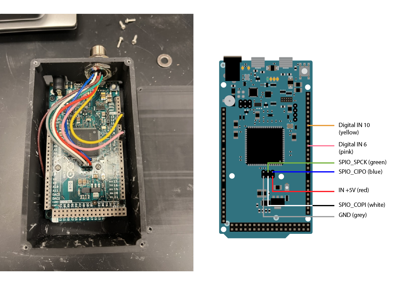
- Have printed the arduino case and screw the arduino. Insert the connector in place and crimp the cables. Make sure to follow the color code and connect the cables to the arduino.
- Cover the case and install the din rail mounting clip. Install the arduino module in the top DIN rail.
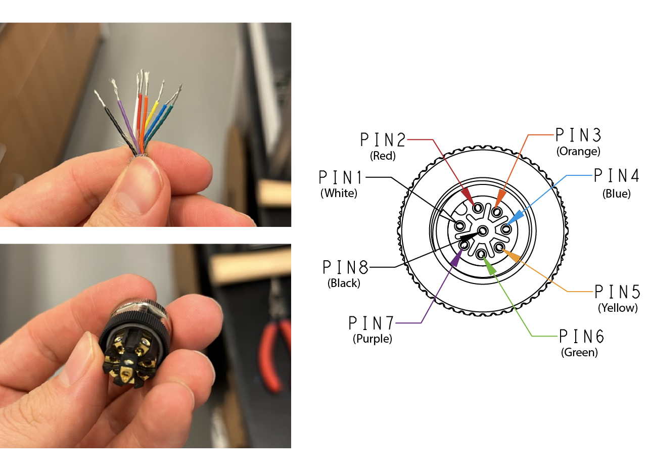
- Make the cable to connect the arduino to the 3D printer cup. Unscrew the outer portion of the connector and insert it into the cable (you need to do this before connecting the cables, otherwise you will not be able to insert the cover and will have to do everything again). Unscrew all the conectors and insert the cable following the color code in the image below, screw them and place the connector cover.
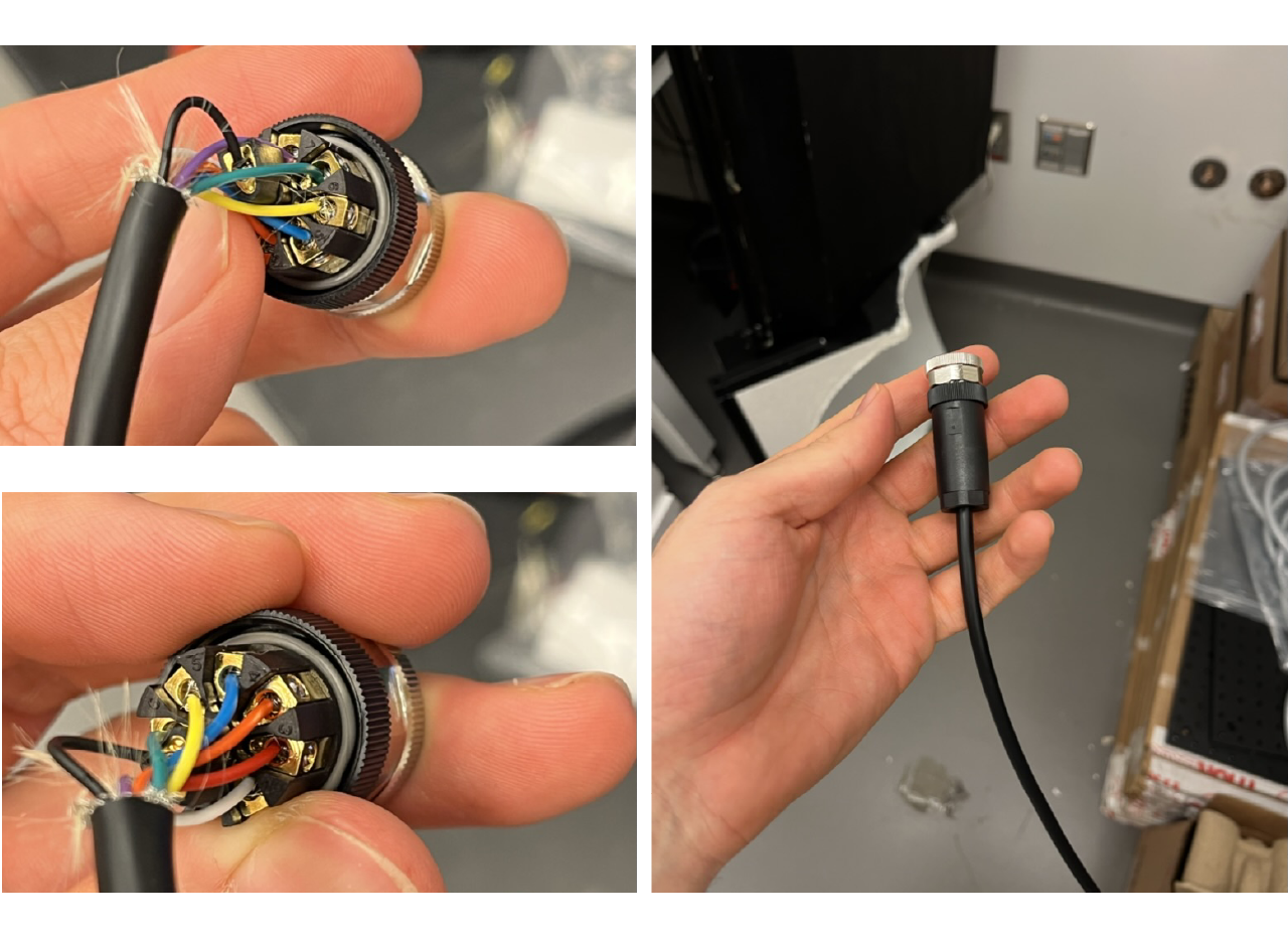
TIP
Place one connector first and connect it to the arduino box placed in the top DIN rail at the outer portion of the rig, then measure the lenght of the cable by inserting into the rig and into the cable carrier. Cut the cable and place the other connector, finally connect it to the 3D printed cup.
- Connect the arduino to the computer using a USB Type-C male to micro-USB Type-B male cable. Or any other cable matching your setup, we do recommend to use a single tether cable or USB 3.0 cable and avoid using either multiple cables or HUBs (or make sure everything is high speed rated).
Programming the Arduino
Download the latest version of the arduino IDE and download the Arduino SAM Boards (32-bits ARM Cortex-M3) toolbox from the boards manager (Tools > Boards > Boards Manager), v1.6.11 has been working for us.
Connect the arduino to the computer using the Programming port (connect the cable to the USB port closest to the circular power connector). The arduino should be listed in the devices at the top of the window as
Arduino Due (Programming port).Either download or open from Matlab the firmware from the repository. The file is inside sensors > ADNS_aout_wUSB_1sensor_or_squal_nativeport folder and is named
ADNS_aout_wUSB_1sensor_or_squal_nativeport.ino. Make sure you have selecteed the board at the top of the window and upload the firmware by pressing the upload button (right arrow icon).Wait until the firmware is uploaded (a message in the terminal of the arduino IDE should confirm this) and disconnect the USB cable from the Programming port and connect it to the Native Port. The arduino should be programmed and working, you can confirm this by running the rig tester and pressing the Arduino detection and sensor quality buttons.
USB HUB and Speaker
- Use double side tape to glue the USB Hub to the cabinet at the top left portion above the DIN rail and connect everything that must be connected there (if using USB or USB powered speakers, the NIDAQ). Use a USB C extension to connect the hub to the computer.
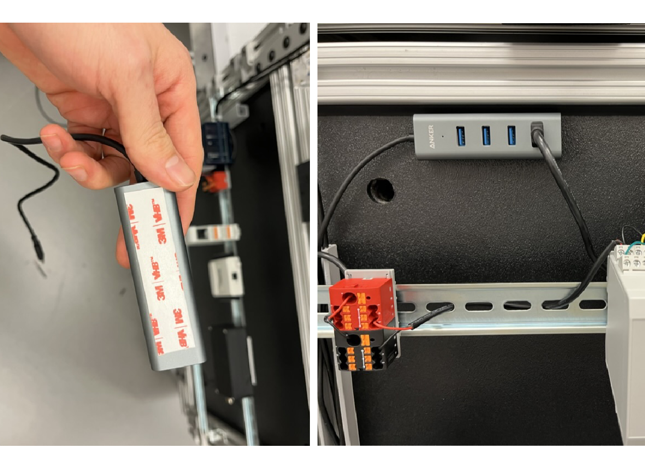
- Place the speaker inside the cabinet and connect to Hub - Make an upper hole on the cabinet for other cables as shown in the picture above. You can use a USB speakers or a desktop speakers and place them on top of the screen plate and connect it to the hub and, if necessary, to the computer audio input.