Cabinet
The cabinet is the box made out of T-slotted frames and panels in which all the components of the training rig are going to be held, and works as an sound insulated space in which the mice wild be performing the tasks. All the control and other modules components are going to be placed on one of the sides of the cabinet, and the projector will be placed at the back of it.
Sound absorbing sheet preparation
We use 75% sound absorbing sheets with adhesive backing that are glued at the internal part of all the panels of the cabinet, which helps to isolate the sound from the lab environment, nevertheless the rooms should be silent and darks when the animals are training.
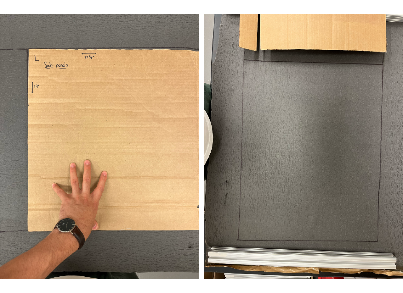
Cut cardboard molds to cut the foams for the panels according to the following table.
| Panel | Size in inches |
|---|---|
| Front doors | 19" x 9 1/2" |
| Back doors | 9 3/8" x 9 3/8 |
| Sides | 19" x 24 3/8" |
| Top | 24 1/2" x 22 3/8" |
| Bottom back | 7 11/16" x 22 3/8" |
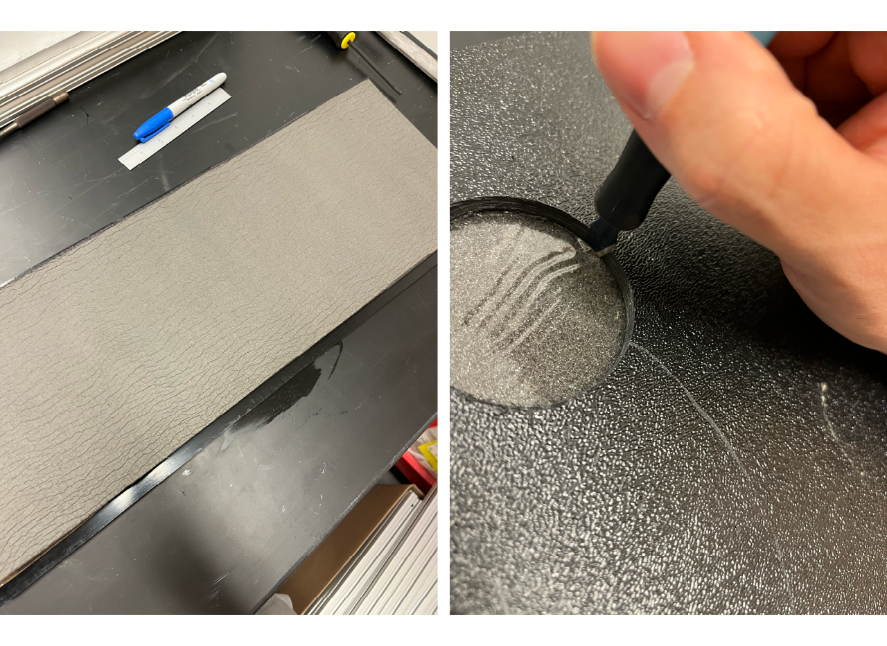
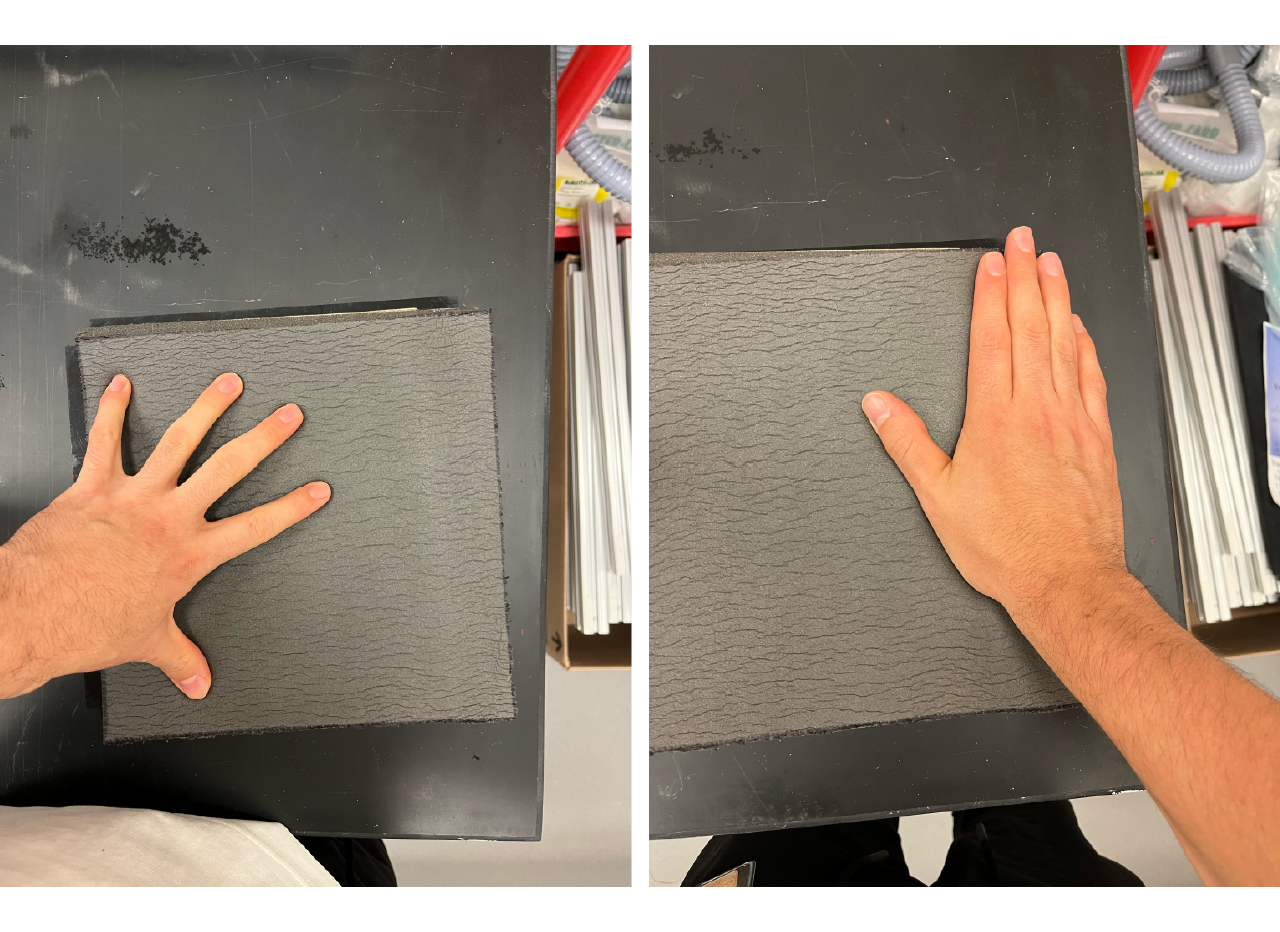
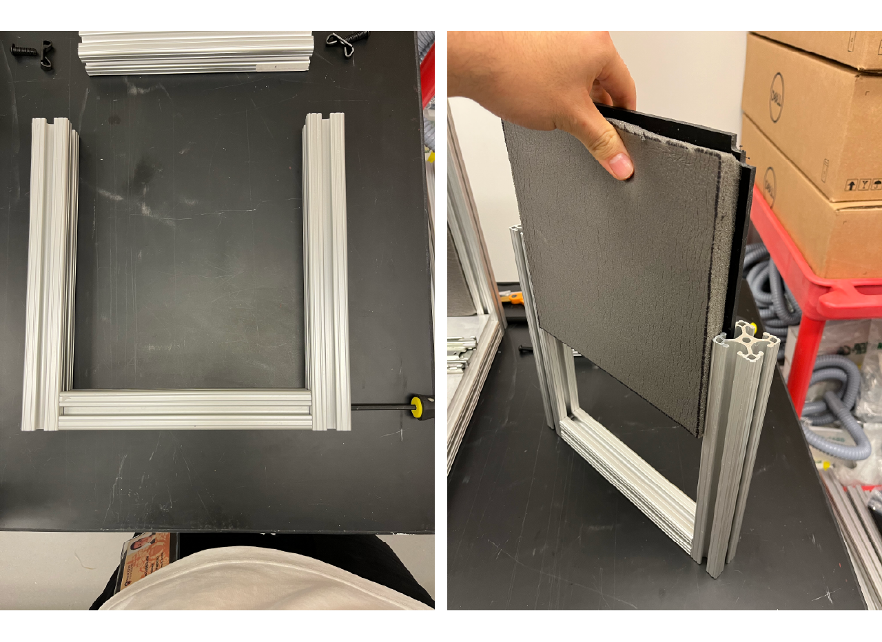
Place the sound absorbing sheet with the foam looking up, then put the mold on top of it and use a black marker to draw through the edges.
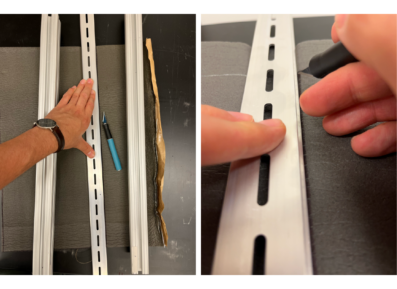
Then place a pair of profiles on top to keep the sheet flat, use a long ruler (or any flat and thin surface, I used a DIN rail to do this) to place it along the marked edges and apply a good ammount of pressure; with a sharp exacto knife cut the sheets following the marker square, we required to pass the knife two times to cut all the way through.
TIP
Constantly change the blades of the exacto knife, a good indicator is if the blade doesn't flow smoothly and sometimes get stuck.
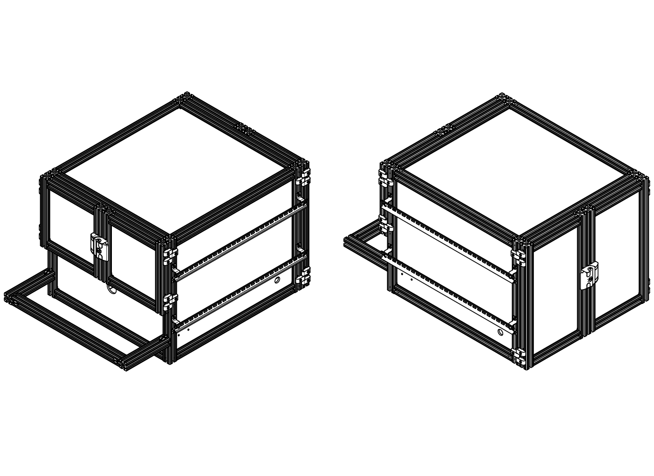
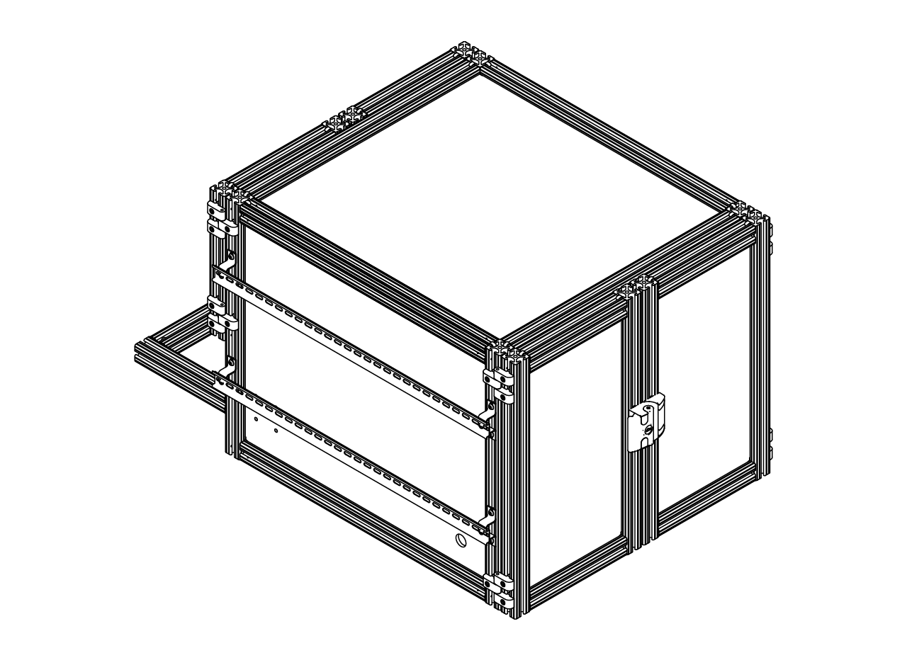
Cabinet assembly
We use 1.5" x 1.5" T-slotted profile to build the frame of the cabinet and 1/4" black harcell ABS (smooth side up) to build the panels. Our supplier the Knotts Company, which is an authorized supplier of 80/20, and sent them the drawings for a quote. Another option is to buy the pieces described in the drawing from other supplier or suppliers, but it will require to do adjustments, and a lot of holes. Assemble the cabinet following the steps below.
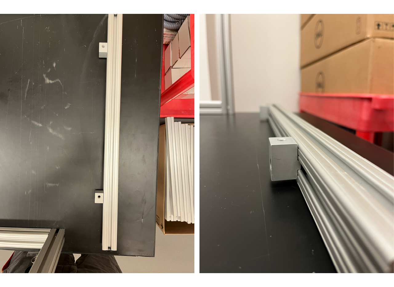
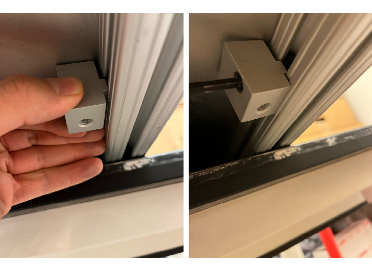
- We start building the cabinet from the bottom up. Slide a pair of bottom plate holders (8020 - 2425) into the 24.5 inches long profile. Make sure the top part of the holder is at the same height as the top part of the profile, as shown in the picture below. Repeat the process for another 24.5" long profile.
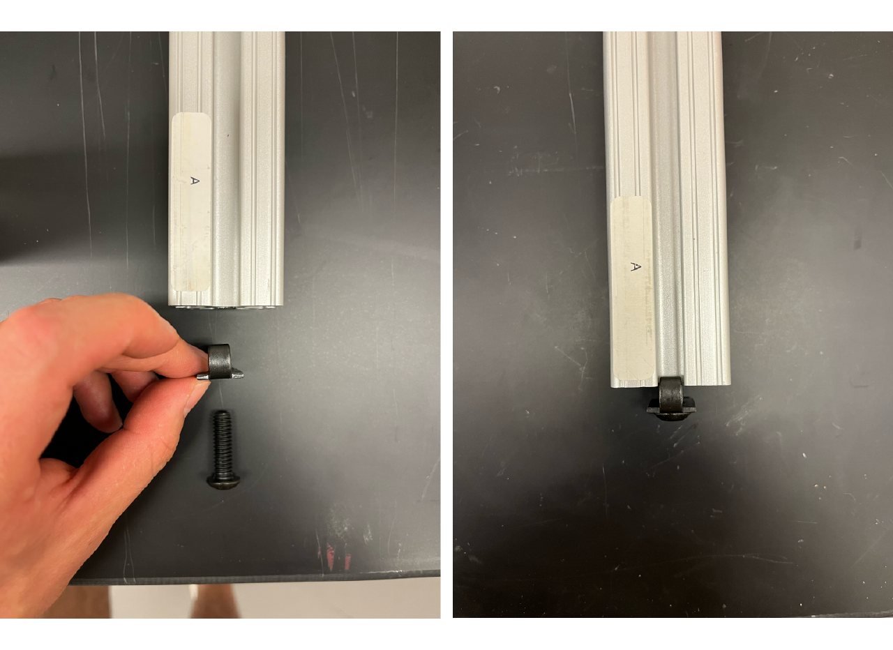
- Insert a standard end fastener to both ends of the 24.5" long profile with the bottom plate holders and to a pair of 22.5" long profiles. First insert the fastener into one of the slots and loosely screw it, repeat the process with the other end making sure the direction of the fastener is the same. Make this for both ends of the 4 profiles.
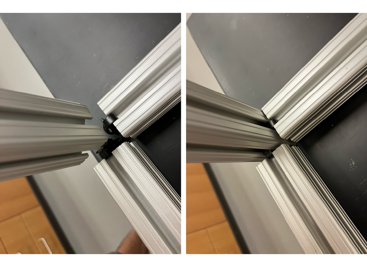
- Arrange the profiles in a square, making sure that the profiles with the plate holders are facing each other to the left and right, and in the correct position (top part of the holder must be at the same height as the top part of the profile); and the 22.5" long profiles are fecing each other at the back and front. Use the 22.05" long profile with holes at 1.5" from the ends to join the front part, and use the 22.05" long profile with holes at 1.5" from both ends and a hole at 11.675" from the top down to join the back part of the rig. Introduce the profiles from the top down and tight screw trough the holes.

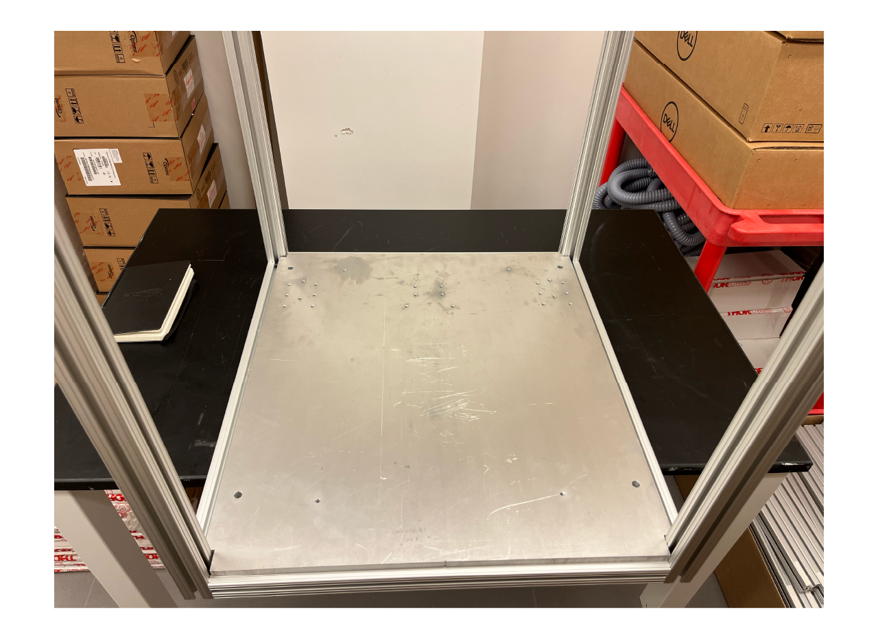
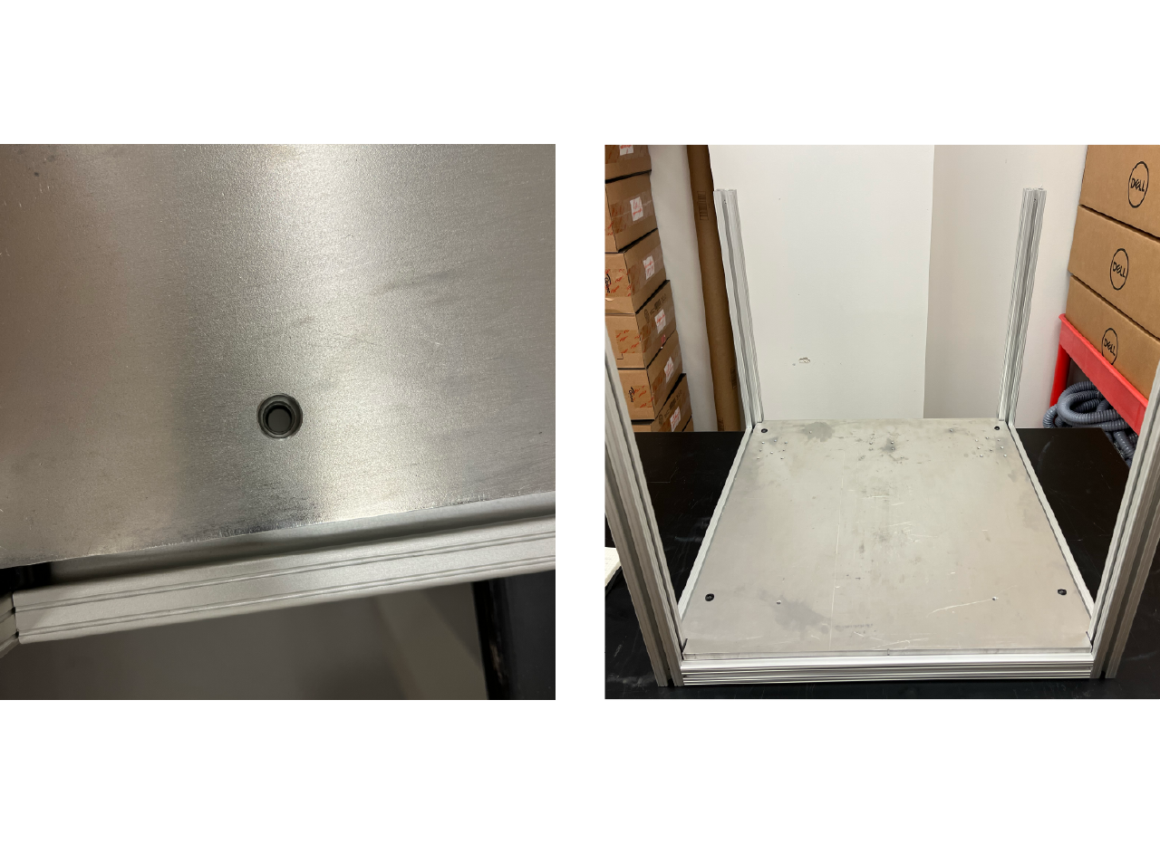
- Place the aluminum bottom plate on top of the frames, slide the bottom plate holders so that they match the plate holes. If the holes don't match in the lateral position, you can unscrew the holders just enough for them to reach the holes. Use 5/16-18 x 0.625" long screws to tight screw the bottom plate to the holders.
TIP
If working on an elevated table, you could push into the air the structure just enough to have visibility on the bottom and match the holders to the holes, then turn around the structure and repeat the process.
TIP
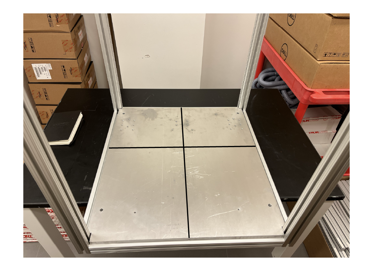
Use a permanent marker to draw two straight lines on top of the botomm plate using the groves at the sides as shown below, this will be extremely useful for the projection calibration.
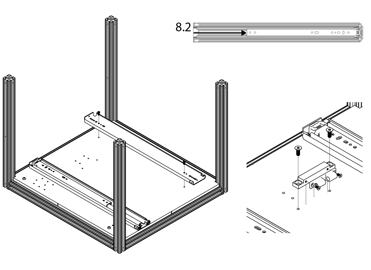
- Cut 8.2 inches to the top base of the drawer slider, then use 1/4"-20 x 1/2" long low-profile screws to install the 26" long steel base-mount drawer sliders. Screw with M4x0.7 mm, 8 mm long screws the latch holder to the latch holder adapter, then use 1/4"-20 x 11/16" flat head screws to attach the latch holder with the adapter to the bottom plate.
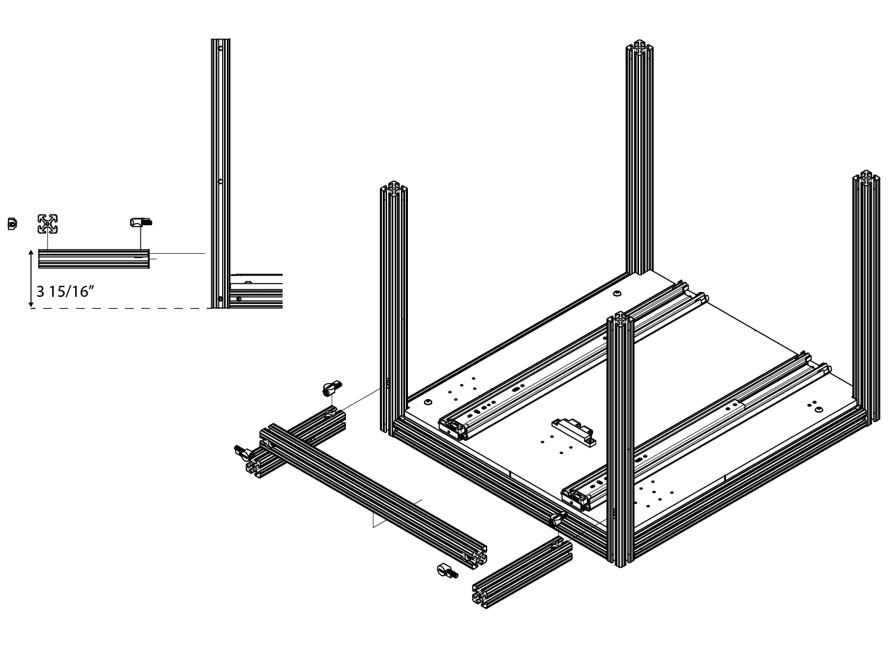
- Install the structure to hold the projector at the back of the rig. Set the height of the structure at 3 15/16" from a flat surfate to the top of the profile.
TIP
You can install the projector bottom plate before measuring to make it easier to set the height.
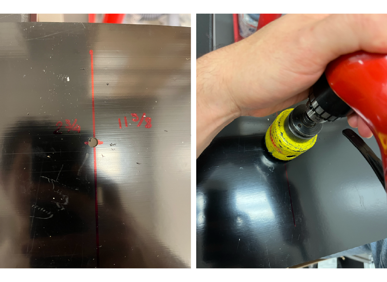
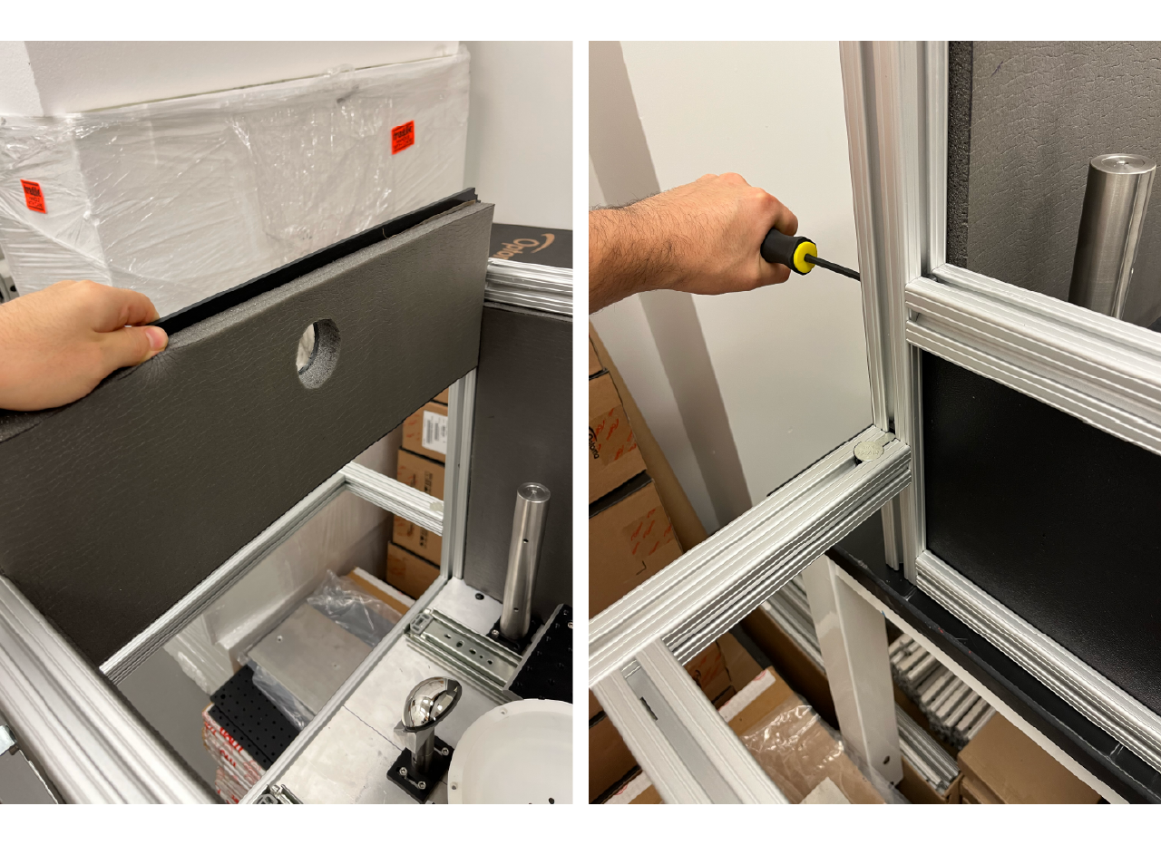
- To install the back panel of the rig, first make the hole for the projection to go trough. Make a hole at 2 3/4" from the top of the panel and at the middle of the panel, or 11 5/8" from the side. We recommend to do a small hole first and then use a 1" drill bit or hole saw.
Install the soundproof foam, then cut the hole from the foam.
TIP
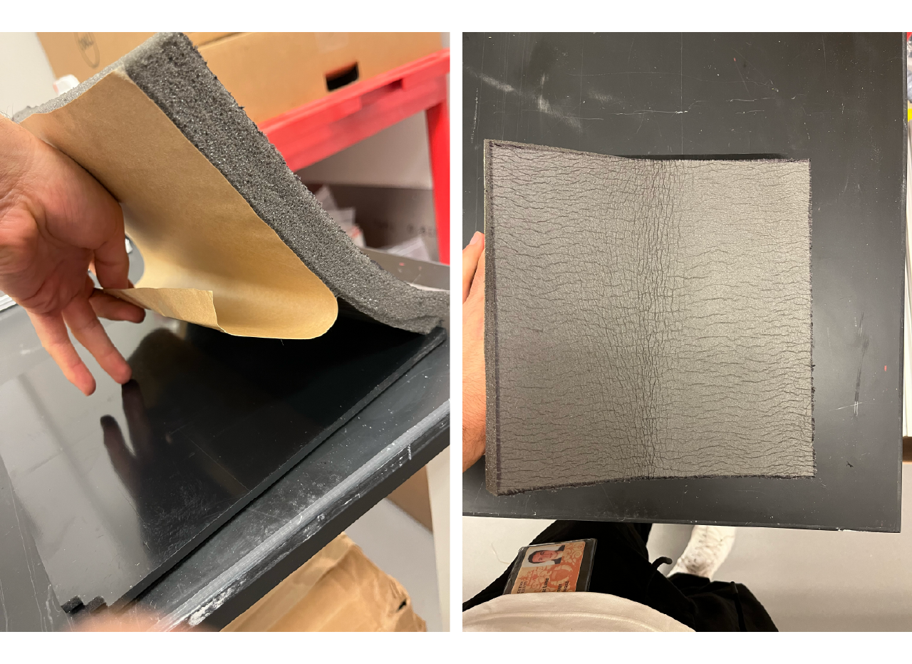
To install the soundproof foam first clean the smooth surface of the panel with a solution of 70% ethanol and let dry. Then remove just a small portion of the protective layer of the adhesive part of the sound absorbing sheet as shown below.
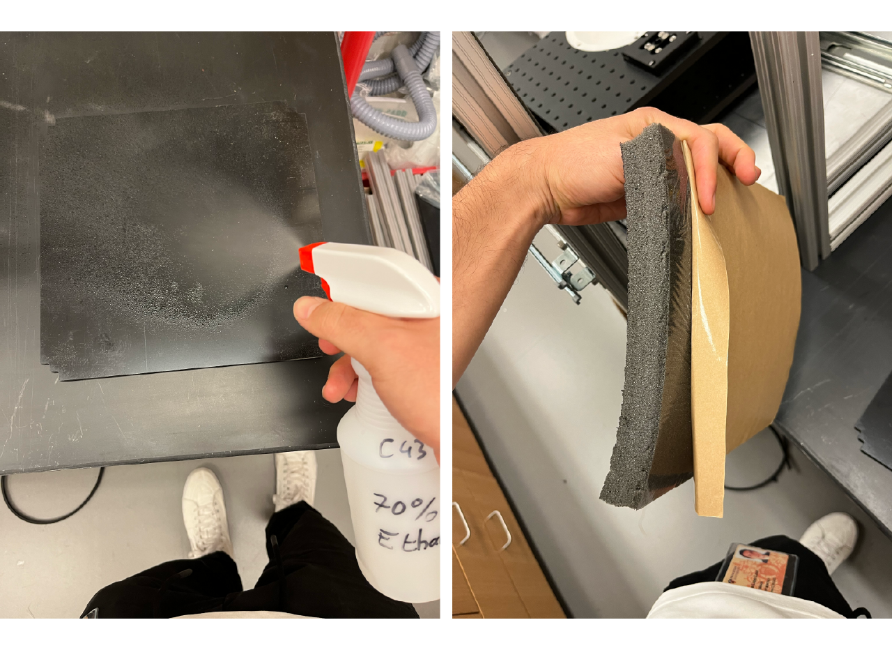
Center the sheet in the panel and paste the uncovered portion by applying pressure along the sheet from the top down.
Remove another small-medium portion of the protective layer and apply pressure onto the panel from the top down, repeat the process until the whole sound absorbing sheet is placed into the panel.
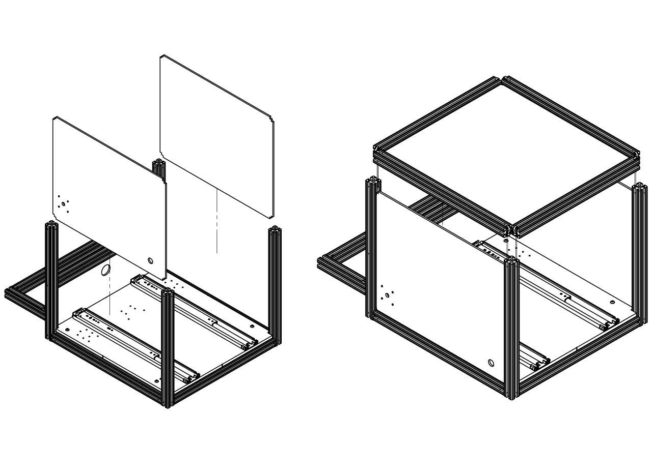
Finally, slide down the panel into the T-slotted profiles at the back of the rig, slidw down a 22.5" profile with fasteners already screwed until it reaches the panel and use the holes at the profiles sides to tighten the screws.
- For the left panel, first cut the square in which the air supply adapter is going to be attached from the sound absorbing sheet, then glue the sheet to the panel and afterwards cut the hole for the cable and hoses (just like we did in the last step). Install both lateral panels first, then arrange two 24.5" long profile and two 22.5" long profile with fasteners loosely screwed at the four sides of the top panel and place them on top of the structure from the top down. Tight the screws when the structure is in place.
TIP
Sometimes when placing the top panel and profiles they don't fit in properly, if you are having troubles fitting them, loose the screws from the bottom of the four corners and the screws from the middle in the back of the frame so you can push down the top structure. Once the top structure is on place, tighten all the screws.
- Assemble the doors by joining a U shape structure first. For the front doors screw at the bottom a 9.65" long profile and a pair of 22.05" long profile, for the back doors form the U shape with 9.65" long profiles. Then slide down the panels with the sound absorbing sheet already in place. After that, screw at the top a 9.65" long profile for both front and back doors. Finally, insert the joining strip along the out edges of the doors.
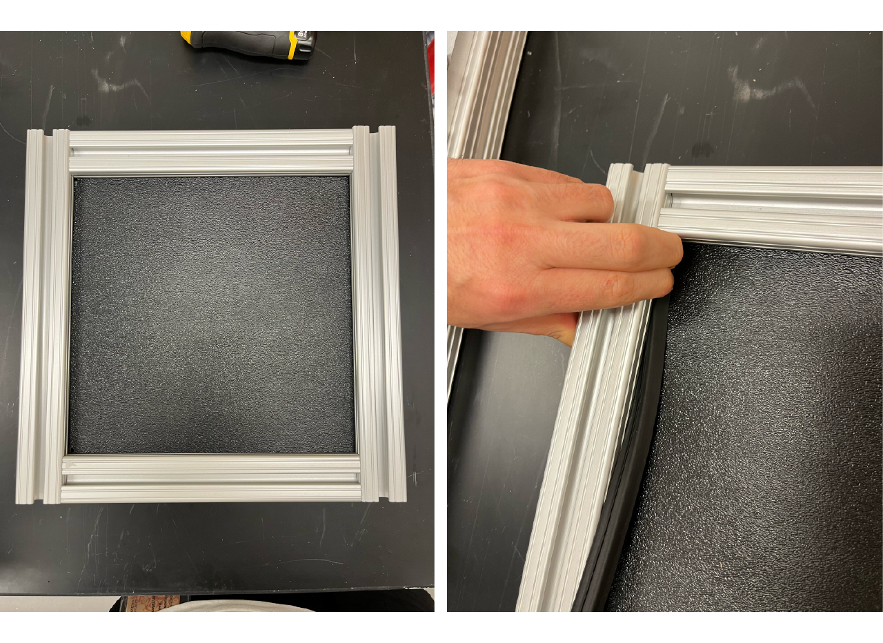
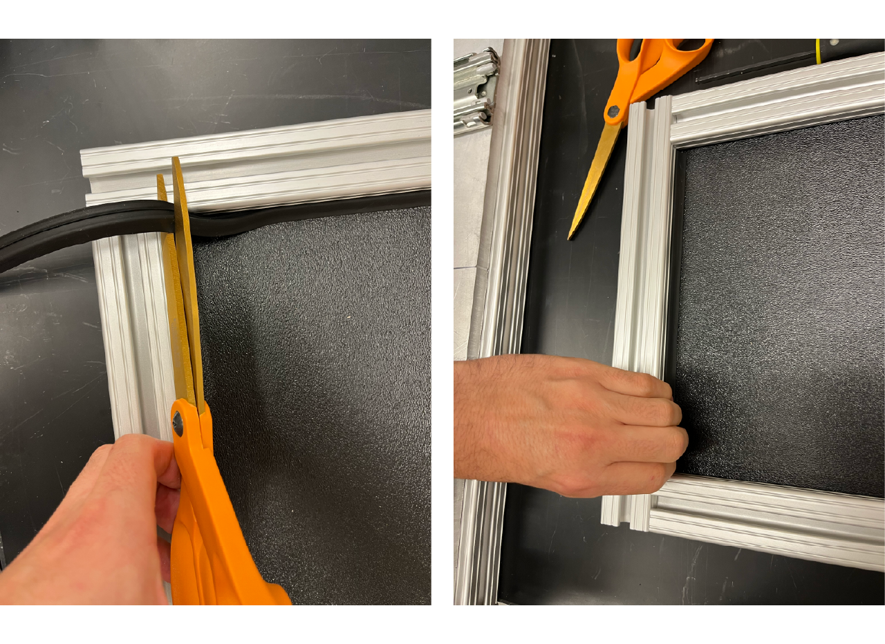
Insert the joining strip to all of the panels in the cabinet.
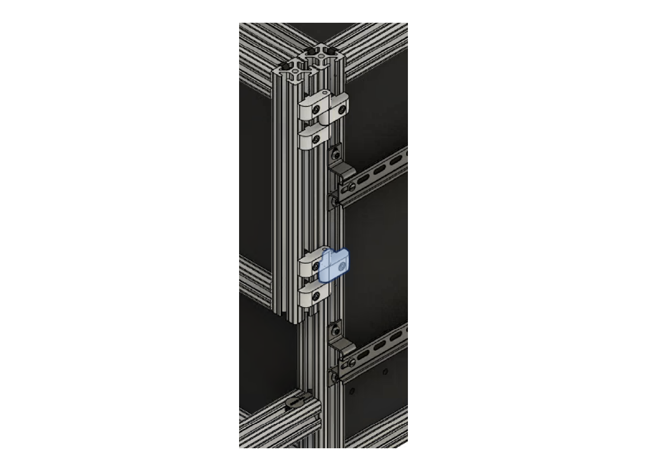
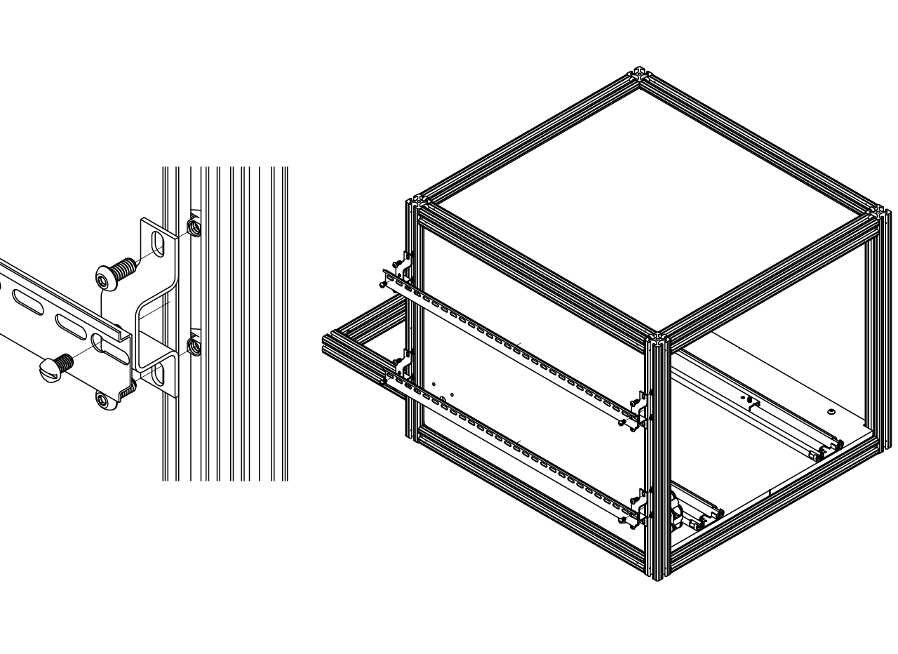
Install the DIN rails by screwing 4 DIN rail mounting adapters into the profile using a T-slotted framing drop-in nut, 1/4"-20 thread size. We buy a 2 m long steel DIN rail and cut two pieces at 27.5". Then attach the pair of DIN rail to the mounting adapters and repeat the process for the other rail.
TIP
Before placing the top DIN rail mounting adapter at the back of the rig, slide down the middle door hinge. Alternatively, you could replace the standard framing nut with a 1/4"-20 T-slotted framing drop-in nut to install that door hinge.
- Install the doors by screwing the lift-off hinges, you will need to place a couple of them for each door at the top and at the bottom. Finally install the lock using a 1/4"-20 screw and 1/4"-20 T-slotted framing drop-in nut.